Creating a 3D tank model
Custom tank models
OLD‑WIKI.WARTHUNDER.COM (DEFUNCT)
Introduction
The result of our work in this file will be a *.max format model and a set of baked textures, each corresponding to the passport (provided materials for the model’s historical accuracy) and to this technical specification. In addition, a separate *.max file with a scene for AO baking, normal maps and ColorID maps from high poly to low poly.
This document describes the creation of a tank or SPG (Self-Propelled Gun). But all the requirements, pipelines, naming rules, resource hierarchies, file structure and so on also apply to other player-controlled ground units.
As an illustrative example, will soon be provided for download.
Model
The final *.max file will contain a tank, damaged tank parts, additional invisible supportive geometry, nodes and bones:
- A model of a whole, undamaged tank with four LODs
- Damaged parts with four LODs (DMG)
- Invisible geometry for calculating hits and damage to the tank’s armor and damaged modules (crew members, engine, fuel tanks, etc.) (DM)
- Supportive nodes for orientating particles and affixing additional modules (tankers, machine guns, machine gun mounts)
- Bones for procedural and physical animation
- Geometry for visualizing hits, damage (XRAY)
Textures
A tank usually has four texture packs:
- the hull
- the turret
- the gun and gun mantlet
- the tracks
In some cases, if a specific tank has no modifications available or if parts of the tank are inseparable (the hull and turret of certain SPGs, for example), we ‘merge’ the textures into a single map. But if several SPGs use one and the same undercarriage, then we lay out this undercarriage in a separate, shared texture and nominally consider it a hull, and the entire part of the hull that is above the undercarriage we lay out in separate, unique textures and nominally consider them turrets.
Each individual case is agreed on in advance.
UV mapping
The greater part of the tank has two texture coordinate channels. The second UV channel is used for placing a camouflage tile on the tank. In principle, only one part of the tank can lack the second texture channel – the tracks. The final version of the second texture channel is made in one of the last phases of model creation – when all the geometry is done in all states and all LODs. Important! In texture mapping on tracks, a tile from 7 to -7 is allowed. In most cases, the full-height tracks do not fit; they have to be broken into two-three segments and the offset of the edge segments of the tracks must be altered with the help of a UVW Xform modifier, so that they don’t exceed their maximum and minimum values.
General requirements for scene

- The final scene must be in a *.max file for 3DSmax2015.
- The model must have a real scale in metric measurement units.
 System Units = Meters.
 1 Unit = 1 cm.
- The tank’s rotational center is at the center of the world (center of the area at the bottom border of the tracks).
- The movement’s tank direction in the *.max file must be on the X axis.
- The tank’s tracks ‘sink’ by 2 cm in height from the level of the center of the world. I.e. the tank stands on the earth on its tracks, not its wheels.
- There must not be modifiers on any objects (objects must be Editable Poly). Objects participating in animation are exceptions, such as antennae or tracks with the Skin modifier.
- Machine guns do not need to be modeled. They are sent along with the passport. They merely need to be placed.
- All objects must have a scale = 100, 100, 100 (use Hierarchy/Reset Scale).
- All objects must have a scale = 100, 100, 100 (use Hierarchy/Reset Scale).
- All individual parts of the tank and modules: turrets, guns, lights, fuel tanks, boxes, covers on exhausts, inventory (shovels, picks, jacks, etc.), lighting implements, track chains, wheels, etc. must be separate objects.
- All objects of the ‘skeleton’ layer must have a block specified in ‘object properties’.
 renderable:b=yes
 cast_shadows:b=yes
 normals:t="disable"
 dir:p3=0, 0, 0
 cast_on_self:b=yes
 unwrapScheme:i=0
 collidable:b=no
 collision:t="box"
 phmat:t=""
 massType:t="none"
 preferMass:b=yes
 mass:r=-1
 density:r=-1
 animated_node:b=yes
 billboard:b=no
 occluder:b=no
In objects of the DM and XRAY layers
 className:t="aces"
 animated_node:b=yes
All objects that can fly off (with the prefix ex_ and the suffix _dstr), wheels, and suspension must be registered in all layers. animated_node:b=yes
Node axes
- For all objects except hatches, direct the axis X along the movement direction and Z upwards.
- For hatches, the X axis is the rotational axis, the Y axis is along the same surface as the hatch, and the Z is inside the hull.
- For all the tank’s elements and nodes, the pivots are located at the object’s rotational center, if the object rotates (wheel, turret, gun, frontal machine gun mantlet, etc.).
- For all nodes apart from particle notes and rotating objects, direct the axis X along the movement direction and Y upwards.
- For all supportive nodes for affixing particles, the X axis is the direction of movement of the particles.
- For machine gun attachment parts, place the axes at their rotational center.
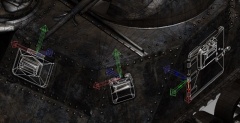
Axis hatches
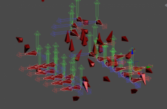
Along the axis of motion
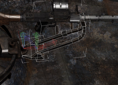
The axes of the machine gun mount


Important! The axes and coordinates of all parts with identical names must correspond in the undamaged model, in the damaged one (DMG), and in the geometry for calculating modules (DM). This is necessary so that when replacing a damaged fender with an undamaged one, for example, the position and rotation of the tank’s parts don’t change.
Naming files, resource hierarchies
File names must begin with a lower case letter. The tank’s name is provided with the passport. Example: m4a2_sherman_1944.max Space marks cannot be used, only underscores. Dashes and hyphens cannot be used, only underscores. Try not to use enumeration. Only use it where it is really necessary – when you have many parts that do not functionally differ from each other and do not particularly influence gameplay.
General provisions for enumerating files and objects inside the *.max: if you use a numerical order, then be sure to use a two-digit value! For example ex_armor_07 is an object inside a *.max file, a piece of external add-on armor, one of many others.
Tank shaders
- dynamic_masked_tank – shader for base objects (body, turret, gun, additional objects on the tank)
- dynamic_tank_atest – shader for tracks (for the right track: texoord_anim -1, for the left: 1)
- dynamic_tank_atest – shader for objects with alpha test.
- dynamic_pbr_glass – shader for light glass.
- dynamic_masked_chrome_bump – shader for lightbulbs and light reflectors.
- dynamic_masked_chrome_bump – shader for barrel rifling.
- gi_black – shader for all objects in the DM layer
- hatching – shader for all objects in the XRAY layer
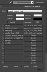
dynamic_masked_atest – shader for base objects (body, turret, gun, additional objects on the tank)
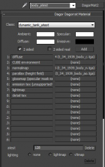
dynamic_tank_atest - shader for tracks (for the right track: texoord_anim -1, for the left: 1)
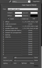
dynamic_tank_atest - shader for objects with alpha test.
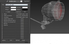
dynamic_pbr_glass – shader for light glass.
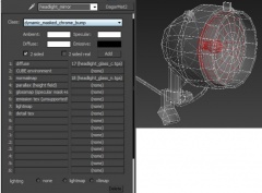
dynamic_masked_chrome_bump – shader for lightbulbs and light reflectors.
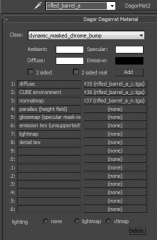
dynamic_masked_chrome_bump – shader for barrel rifling.
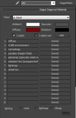
gi_black – shader for all objects in the DM layer
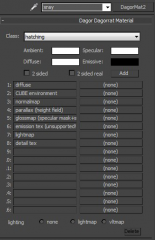
hatching – shader for all objects in the XRAY layer


Building a *.max file and geometry requirements
Building a *.max file and naming objects
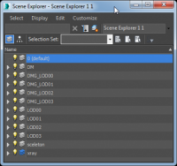
All objects in the *.max file must be in the correct layers. Our final file universally contains the following: Geometry of the tank with four LODs. Geometry of damaged parts with four LODs (DMG). Supportive geometry for calculating damage (DM). Nodes for binding effects, additional modules, animation of tracks and antennas. Supportive geometry for visualizing hits (XRAY).
All supportive nodes and bones for animation lie in a separate layer: skeleton.
| Names of objects with visible geometry in the file: | |
|---|---|
| Object | Object Name |
| Hull | body |
| Turret | turret |
| Mobile part of gun (animation with recoil from shot) | gun_barrel |
| Gun mantlet | gun_mask |
| Machine gun mantlet | mg_mask |
| Hatches | hatch |
| Track | track |
| Antenna | Antenna |
| Lamps, headlights, spotlights | ex_lantern |
| External static mortar, grenade launcher, mine launcher | ex_mortar |
| Pieces of external decor influencing the armor level. Such as spare tracks, sandbags, boards, add-on armor screens. | ex_armor |
| External spare fuel tanks | ex_fuel_tank |
| Pieces of external decor that do not influence the armor level and do not have any effect on gameplay functions (shovels, picks, buckets, etc.) | ex_decor |
| Wheel, roller (more detail in the subsection Wheels and undercarriage). | wheel |
| Mobile element of the undercarriage (more detail in the subsection Wheels and undercarriage). | suspension4 |
| Smoke generators | ex_smoke |
If the file contains several objects of a single type, and separating them into left-right is important, then add suffixes (with the exception of hatch):
 _r – for objects on the right side of the tank
 _l – for objects on the left side of the tank
This is important for tracks, for example:
track_r, track_l
If the file has several objects of a single type, add an ordered number on the end. If possible, number them from front to back based on the tank’s direction of movement. For example, a multi-turreted tank will have the turrets:
turret_01, turret_02
If the tank has several turrets, then the enumeration of the guns and gun mantlets must correspond to the enumeration of the turrets. If the tank has external engines or lights, that means they will be separate detachable modules. At the same time, they participate in the game process and their names must indicate their position.
Using the Tiger Ausf. H1 as an example, the enumeration will look like this:

Firstly, if they are on the hull and the turret, this must be reflected in the title. Secondly, their position based on the tank’s direction of movement must be indicated (r or l), and thirdly – they must be numbered. Based on these requirements, mortars and lights will be numbered like so:
- ex_mortar_turret_r_01
- ex_mortar_turret_r_02
- ex_mortar_turret_r_03
- ex_mortar_body_r_01
- ex_mortar_body_r_02
- ex_mortar_body_r_03
If this tank had one light or spotlight on the turret roof, it would be called: ex_lantern_turret , while a light on the body would be: ex_lantern_body Lights located on the front end of the tank are called ex_lantern_01, ex_lantern_02, etc. Lights located on the rear end of the tank are called ex_lantern_b_01, ex_lantern_b_02, etc.
In the case of decor elements (ex_decor), objects in one file can be simultaneously named either with the suffix _r or _l or without a side indication. The logical differentiation is this: if the decor is on the side and at the same time has a brother on the opposite side, then there is a suffix. If the object has no symmetrical relative, then there is no suffix. For example:
The Tiger’s fenders are called: ex_decor_l_01 and ex_decor_r_01
But its shovels and so on on the hull around the turret are: Ex_decor_01
Important notes on names:
- The names of all objects consist of lowercase letters, do not use uppercase.
- Do not use space marks – only underscores.
- In the names of objects whose locations do not particularly matter (inventory such as shovels and jacks, for example), there is no need to use suffixes to indicate their location on the tank (r or l). It is enough #to simply enumerate them.
- The names of nodes must strictly match for all LODs and all states in all layers – i.e. the tank’s turret must be called ‘turret’ in all layers, regardless of which LOD it is.
- Any potential deviation from the naming system must be discussed.
Wheels and suspension:
- Each wheel and all mobile parts of the suspension must be separate objects with pivots and a center of the rotational axis.
- Names for wheels and suspensions must be written like so: a wheel is called wheel, and a suspension is called suspension.
- All wheels and the suspension must have the suffixes _r_ and _l_ for each side of the tank. For example: wheel_r_01 is a right wheel, and wheel_l_01 is a left wheel.
- Numbering increases in ascending order from the front of the tank to the rear.
- The numbering of lower track wheels, supporting wheels, and suspension may differ. In other words, it may happen that one suspension has two wheels at once. In this case, suspension_r_03 will have the wheels wheel_r_05 and #wheel_r_06.
- The wheels from the upper row, which the track ‘slides’ along in the opposite direction, have the suffix _top_ and the same numbering as the roller wheels: wheel_r_top_04 is the upper wheel on the right side and the fourth #in the row.
- If the wheel is a drive wheel, use the suffix _drive instead of a number. For example, wheel_r_drive is a drive wheel on the right side.
- If the wheel is a trailing wheel if looked at from the front of the tank to the rear, but is not a drive wheel, give it the suffix _back. For example: wheel_r_back is the last in order, non-drive wheel on the right side.
- If the wheel is the first in order from the front of the tank to the rear, but is not a drive wheel, give it the suffix _front. For example: wheel_r_front is the first in order, non-drive wheel on the right side.
Bones. Animation skeleton
When we talk about linking objects to bones or to each other, we always mean that this hierarchy should be maintained in all LODs, i.e. in all layers.
Bones lie in the separate skeleton layer.
The names of all bones apart from the root bone begin with the prefix bones_. If necessary, they can end with an ordered number – if For example:
bone_wheel_r_01_01
this is the bone responsible for animating vertices on the track right below the wheel
wheel_r_01_01
The overall structure of the tank’s skeleton looks like this:
| Bone function | Bone name |
|---|---|
| Root bone. Located at null coordinates in the file, turned on axis X by axis X in the direction of the tank and axis Y upwards. | root |
| The bone to which the turret and all its parts are linked is located in the turret’s center of rotation and turned by the X axis precisely along the direction of the turret, and by the Y axis upwards. I.e. if the tank’s turret is on the side, aiming to the side instead of toward the tank’s direction of movement, then the X axis will also ‘look’ in the same direction. This bone is a child of the root bone. | bone_turret |
| The bone to which the gun mantlet, twin machine gun and all other parts animated along with the main gun are linked. Located at the main gun’s center of rotation. Turned by the X axis in the direction of the gun, and by the Y axis upwards. This bone is a child of the root bone. | bone_gun |
| The bone to which the gun barrel is linked. Participates in the animation of the gun’s recoil when firing. In the center of the cylinder somewhere near the base of the gun. Turned by the X axis precisely in the direction of the main gun and by the Y axis upwards. | bone_gun_barrel |
| A bone for attaching a mounting under a machine gun. | bone_mg_mount |
| A root bone for procedural physics animations at the base of an antenna. | bone_antenna |
| A bone at the end of an antenna for procedural physics animations. Attached to the antenna root bone. | bone_phx_antenna |
If certain bones are procedurally animated according to physics (as with a bone at the end of an antenna), then we add a clarification after the _bone suffix: _phx Cases when we use procedural physics animation:
- antennae
- upper overhanging part of track
- cloth/canvas cover on the gun mantlet
- springs (on suspension, on gun), but only those which move in time to the movement of the tank or gun.
Important! For physical animation, you must have a vector along two bones – from the procedural rotational base to the end. I.e. create two bones for each part which has a physics animation. The root bone in this mini-hierarchy has no _phx suffix, only the last bone does. We do not plan to have more than two bones to animate a single object.
Bone hooks for attaching machine guns:
| Bone function | Bone name |
|---|---|
| Twin machine gun. | bone_mg_gun_twin |
| Machine gun in tank body. | bone_mg_body |
| Machine gun in tank turret, not twinned with main gun. | bone_mg_turret |
| Node for animating a single machine gun. Hinged system, i.e. a solid mantlet that rotates on all axes. | bone_mg_body_mask_sphere |
| Node for animating a single machine gun. The part of the mantlet that moves vertically. | bone_mg_body_mask_v |
| Node for animating a single machine gun. The part of the mantlet that moves horizontally. | bone_mg_body_mask_h |
The last three bones have _body_ in their name. If an untwinned machine gun is in the tank’s hull, but is a frontal machine gun on the tank’s turret (for example on the IS-2), then the location specification will be _turret_ instead of _body_. Bones can be enumerated when necessary if there are several turrets. Or if there are several frontal machine guns.
EMTR Supportive nodes for attaching particles and additional external modules
In places where effect emitters will be created during movement, supportive nodes must be created in 3DSmax. In our case, these are bone objects. The nodes must be directed along axis X in the direction of the particles’ movement.
The node’s function will be tied to the function of the object to which the node is attached, but sometimes they are independent. Hence the requirement: dependent nodes must carry a link to the object to which they are attached in their name. Independent nodes must be named by their function and numbered.
Function and names of dependent nodes:
| Node function | Node name |
|---|---|
| Main gun shot | emtr_gun_flame |
| Mortar shot | emtr_mortar_flame |
| Machine gun shot | emtr_mg_flame |
| Light from a lantern or spotlight | emtr_lantern |
| A trail of fire and smoke from a blown-off tank part | emtr_<part name>_explosion |
- - if the parent of the dependent node has a number in the title, the node copies it.
Function and names of independent nodes:
| Node function | Node name |
|---|---|
| Exhaust smoke | emtr_exhaust_01(02,03 etc. if there are several exhaust outlets) |
| Fire in the engine compartment | emtr_fire_engine |
| Fire outbreak in ammo rack | emtr_fire_ammo |
| Ammo rack explosion center, full destruction of tank | emtr_explosion_center |
| Fire on destroyed tank | emtr_fire_dmg |
| Small source of fire on destroyed tank | emtr_fire_small_dmg |
| Smoke on destroyed tank | emtr_smoke_dmg |
| Small source of smoke on destroyed tank | emtr_smoke_small_dmg |
| Fire on torn-off external fuel tank | emtr_<name of fuel tank> |
Function and names of track nodes:
| Node function | Node name |
|---|---|
| Dirt flying backwards from underneath the right track when moving forwards. | emtr_track_r_back_bottom |
| Dirt flying forwards from underneath the right track when moving backwards. | emtr_track_r_front_bottom |
| Dirt flying backwards from above the right track when moving backwards. | emtr_track_r_back_top |
| Dirt flying forwards from above the right track when moving forwards. | emtr_track_r_front_top |
We use the same ones for the left track, simply with _l_ instead of _r_. All supportive modes for attaching emitters must be linked to objects based on a logical hierarchy. I.e. if this node turns with the turret, gun or other object – it is attached to it. If the node is responsible for attaching a smoke or fire emitter on a part of the tank that can be blown off, the node is attached to this dmg object.
EX Decorators, external modules
All external elements of the tank that can be shot off by a machine gun or main gun must be separate objects and their names must start with the prefix ex_.
If the element is tilted (for example a shovel) then the object’s pivot must correspond to the angle of tilt.
The types of these elements and the rules for naming them are described in the section “Names of objects with visible geometry in the file”.
Each of these objects has its own dm and dmg model.
DM Supportive geometry for calculating hits, damage
Apart from the tank, the final *.max file will contain a geometric pattern that we use to calculate hits on the tank – the Damage Model, or DM.
Since players can see this geometric pattern, it is very important that all angles correspond to the tank’s passport data.
Each individual object has its own corresponding DM. List of names for all modules in a separate file
These are simplified objects.
Principle of creating geometry


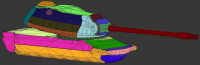
- Make a geometric pattern primitive in shape that repeats the main contours of the tank. For the tank’s hull and turret, you can take the first LOD and cut it into pieces. It is very important that the armor angles are the same as in the vehicle’s passport and schematics.
- Name these objects the same as the objects to which they correspond, but with the suffix *_dm. For example, for the object wheel_l_1, the DM will be called wheel_l_1_dm, and the body object’s DM will be body_dm. Included is a file of names that can be used for the DMs of tank parts.
- The thickness of the armor in the hull, turret and gun differ in terms of area, and we need to show this in the DM. The hull, turret, gun mantlet etc. must be cut into pieces. The cuts must be made based on the thickness indicated in the passport.
- Name all the resulting pieces according to the list shown below. The location and name may vary in all tanks. This is discussed separately when necessary.
- Internal modules must be located in accordance with the passport and references.
- Cut a hole for the barrel in the gun mantlet.
- The geometry must describe the module from the XRAY layer.
- The barrel must reach the breech housing of the gun.
- There must not be any gaps between the parts.
- The part must have 2 walls (i.e. have a thickness).
List of parts for armor layout
If a dm is responsible for calculating damage to an individual module, that means its title copies the module and has the suffix _dm. For example, a fuel tank with the name:
ex_fuel_tank_01
has a dm with the name:
ex_fuel_tank_01_dm
The hull is split into two large areas: The upper part – the turret platform The lower part above the suspension – the hull Turret platform armor:
| DM function | DM name |
|---|---|
| Turret platform side armor, both left and right. | superstructure_side_dm |
| Wheel arch cover armor, the upper vertical part of the armor of the turret platform above the tracks | superstructure_bottom_dm |
| Frontal armor of the turret platform | superstructure_front_dm |
| Rear armor of the turret platform | superstructure_back_dm |
| Roof of the turret platform (the plate on which the turret sits) | superstructure_top_dm |
Hull armor:
| DM function | DM name |
|---|---|
| Side hull armor, both left and right (usually the side is located behind the tracks) | body_side_dm |
| Tank underside armor | body_bottom_dm |
| Front hull armor | body_front_dm |
| Rear hull armor | body_back_dm |
| Hull roof (horizontal armor at the front of the hull on the Pz.IV, for example) | body_top_dm |
Turret armor:
| DM function | DM name |
|---|---|
| Frontal turret armor | turret_front_dm |
| Lower turret armor | turret_bottom_dm |
| Side turret armor | turret_side_dm |
| Roof turret armor, including hatches on turret | turret_top_dm |
| Rear turret armor | turret_back_dm |
| Command cupola armor (vertical part of armor) | turret_commander_dm |
Gun armor:
| DM function | DM name |
|---|---|
| Gun mantlet armor: | gun_mask_dm |
| Gun | gun_barrel_dm |
Internal damaged vehicle modules

A list of DMs of invisible internal modules:
| DM function | DM name |
|---|---|
| Engine | engine_dm |
| Fuel tanks | fuel_tank_dm |
| Transmission | transmission_dm |
| Ammunition in hull | ammo_body_dm |
| Ammunition in turret | ammo_turret_dm |
| Turret horizontal turning mechanism | drive_turret_h_dm |
| Vertical aiming mechanism | drive_turret_v_dm |
| Gun breech | cannon_breech_dm |
| Optical instruments for observation and aiming | optic_dm |
| Radio | radio_station_dm |
List of crew DMs:
| DM function | DM name |
|---|---|
| Tank commander | commander_dm |
| Gunner | gunner_dm |
| Driver | driver_dm |
| Gunner / Radio operator | machine_gunner_dm |
| Loader | loader_dm |
Mandatory requirement for DMs: all normals in the geometry must be aimed at the external side.
There can be several of some modules, so suffixes must be enumerated where necessary. For example, if we make several engines, we call them engine_01_dm, engine_02_dm etc. The same for the crew – if there are several loaders, their names will be loader_01_dm, loader_02_dm etc.
If the DM geometry is responsible for penetrability of an animated object, as in the case of the turret and gun – the DM is attached to the same nodes as the geometry of the turret and gun. The DMs of various turret modules are also attached to the turret node – the crew members, ammunition racks, optical instruments, externally suspended modules on the turret etc. (i.e. everything that can rotate with the turret).
CLS – geometry for collisions with outside world
The tank collides with the earth’s surface using a DM of the wheel modules. Additional geometry for collision with the outside world is required for:
- the hull
- the turret
- the gun
In the scene, this geometry is kept in one layer along with the DM. Collision geometry is simple topology! The collision geometry is called:
 cls_body
 cls_turret
 cls_gun
When one box is not enough to convey the general shapes of the hull or turret, we make several boxes and enumerate them like so:
 cls_body_01
 cls_body_02
 cls_body_03
etc. Important! When turning a box, move the entire object, not the elements within the object. The box’s direction of pivot must correspond to the geometry’s incline.
XRAY Supportive geometry for visualizing hits, damage
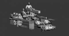
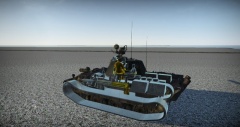
Principle of creating geometry

- We place modules in accordance with the passport and with provided references (the same for modules for the DM layer). For the majority of tanks, all you need to do is place already existing modules, but in some cases it will be necessary to model internal modules (non-standard engines, transmission etc.). This is discussed when necessary separately.
- Name these objects the same as the objects from the DM layer to which they correspond, but with the suffix *_xray. For example, transmission_dm should be called transmission_xray.
- Parts should not intersect each other (in very small tanks, a small amount of geometric intersection is acceptable).
- The crew can be scaled to within 5%.
- The number, size and location of shells must correspond to the passport data (in the case of tanks with separate loading, both the shells and charges will need to be modeled). The placement of the shells is described in profile. The ammunition complement must also be divided into modules of 8-15 shells each (they are usually laid out like that). For separately loaded ammunition, the amount of shells and charges in the modules must be identical.
Mandatory requirement for XRAY: all normals in the geometry must be aimed at the external side! There can be several of some modules, so suffixes must be enumerated where necessary. For example, if we make several engines, we call them ammo_body_01_xray, ammo_body_02_xray etc. The same for the crew – if there are several loaders, their names will be loader_01_xray, loader_02_xray etc.
DMG Models for destroyed tank parts
When the tank or an individual internal module is damaged or destroyed, it is replaced by the damaged model – dmg. A damaged model of any part replaces the geometry of the entire module when it is damaged. A damaged model does not have its own separate set of textures – the base texture of the tank is used. For the entire dmg geometry, we make LODs, just as we make them for a whole, undamaged geometry as well. The dmg geometry of tracks must have a skin modifier, otherwise the tank’s tracks would disappear when damaged instead of being replaced by the dmg model. The dmg geometry lies in separate layers in the *.max files. See section: 2.1. Building a *.max file and naming objects Model dmg types
| Function | Name |
|---|---|
| An undamaged model is replaced with a dmg and remains in the same place. Usually, these are parts that are welded to the tank, which deteriorate from hits but do not fly off. | Duplicates the name of the undamaged model, with the suffix _dmg. |
| The undamaged model is replaced with the dmg and flies off the tank. These are usually non-welded modules such as inventory (shovels, picks). | Duplicates the name of the undamaged model, but with the suffix _dstr. |
| One undamaged model is replaced by two dmg models: one part remains on the tank, the second flies off. For example, a spare external fuel tank with fuel. | The part that remains on the tank copies the name of the undamaged model with the suffix _dmg, and the part that flies off copies the name of the undamaged model, but with the suffix _dstr. |
In summary:
- A dmg geometry which remains in the same position as an undamaged model copies the name of the undamaged geometry.
- The suffix _dstr has the dmg geometry that flies off the hull.
Some elements split into two pieces after destruction, being replaced with several dmg objects. For example, an external fuel container on the tank: ex_fuel_tank_02 in the explosion, it is replaced with the following dmg geometry: ex_fuel_tank_02 – the part of the container and fixings that remain on the hull. ex_fuel_tank_02_dstr – the part of the container that flies off.
Some elements in the dmg model do not have an independent and separate ancestor in the entire geometry. For example, a cover that flies off the engine compartment is a part of the hull in the whole geometry, but during an explosion, it flies away. This new geometry can have any sane descriptive title, but it must end on _dstr.
We do not plan to separate any individual elements by more than two parts – with the original name and _dstr. I.e. a single object cannot have several _dstr suffixes.
All objects with the _dstr suffix fly off in various directions during an explosion and have attached nodes for emitters for fire and smoke trails.
At the same time, certain dmg models that do not fly off the hull, but remain with it, can also have attached nodes for emitters. For example, a fuel tank – one part flies off, leaving a smoke trail behind it, but the second part continues to burn.
More about this in the section: 2.3. EMTR. Supportive nodes for attaching particles and additional external modules
Low poly
The model must not exceed 140k triangles in LOD00, but it is not necessary to strive to make each tank fit this polygon limit, it is necessary to use polygons properly. A model includes:
- banded tracks
- tank hull with suspension, wheel rollers and internals
- turret with internals
- gun with breech
The tank should be modeled based on the benchmark photograph indicated in the passport. For modeling, it is best to use factory schematics with sizes, but alas, far from all tanks still have such schematics available, and usually we have to use outline drawings which are very inaccurate. For this reason, it is important to double-check every modeled part based on available photographs. When there are no precise sizes, we use proportions of size juxtapositions on the photograph and the model in Photoshop. This is the best way to check models, and far fewer corrections are required when this method is used.
General requirements
All elements that influence the tank’s silhouette must be modeled in the null LOD. All levers, hatches, lights and all inventory on the hull such as shovels and crowbars. This requirement concerns all ‘convex’ elements and large ‘concave’ elements. The only thing we don’t model are very small elements such as rivets, welds and other tiny things. But if the tank itself is weakly detailed and there is a large surplus of polygons, we can model things like rivets and screws.
Large elements should not be made ‘flat’, i.e. duplicated and attached to the normals of the polygons! The null LOD contains only the faithful volume, all elements have their own thickness. An exception is grills with an alpha test.
Lateral splits must be sufficient on soft bends, so that they can be perceived as smooth even without a normal map.
What we are aiming for: a low-poly model without normal maps, covered with a simple gray diffuse, that should look accurate and detailed, without corruption or fractures in the vertex normals.
We use various smoothing groups if the edge of the model is hard. This must be taken into account when baking the normal maps!
The greatest detalization in a low-poly model must be in the turret, where the in-game camera may be moved at point-blank range.
We faithfully extrude the internal walls of the turret or the hull to the thickness of the armor in that spot. For example, here is the 75 mm turret wall of the KV-2:
We extrude all walls based on the passport thickness, then carefully stitch them together to eliminate skew and bending. This is all done for a more accurate internal section, so as to more accurately make/house equipment for the XRAY, seat the dummy crew members and have an accurate DM.
This is a little more complex to do for cast hulls or turrets (for example the turrets of the T-54, T-10, IS-3 etc.), where the armor zones have flowing inward/outward tapers. For this reason, we have to break them into a large number of extruded sections and then collapse the resulting steps at the edges.
On the external sections, all parts larger than nuts and bolts are modeled with the exception of hidden or poorly visible parts (pieces of the suspension covered by wheel rollers), where we economize on polygons.
During modeling, use instances for all identical/symmetrical objects right up to the creation of the texture map.
During modeling, immediately construct edges in improper polygons by breaking them into proper ones. This directly affects the baking of the AO and normal maps due to crooked projection.
Immediately set smoothing groups (hard/soft edges for maya) on all polygons, since catching these ‘blocks’ during upload to the engine later is not a very pleasant process.
All large hatches are faithfully modeled with the ability to be opened.
Exceptions are made for evacuation and maintenance hatches on the bottom and for hatches for which it is unknown what is underneath them (these are usually found above the engine transmission compartment).
The internal section is modeled on the base sizes and large parts. That which is more directly visible from the tank hatches is done in more detail. Usually, 5-8 thousand triangles are spent on all the tank’s internals.

An aperture in the turret is modeled for the gun and gun mantlet. The trunnions should be made and checked at this same stage, so that the gun mantlet turns in them to the passport angles.
Detalization
In modeling cylindrical objects, we choose number of edges as a multiple of 2 or 6, i.e. 2, 4, 6, 8, 12, 16, 18, 24, 32, 36, 48, 64 etc. With the rare exception that, for example, leading wheels may use 20, 28 or 40 edges. Using an odd number is forbidden, since LOD01 will be curved as a result. In modeling the gun barrel, we orient ourselves based on the caliber and select the corresponding number of edges:
- <30 mm – 12 edges.
- 30-45 mm – 16 edges.
- 45-120mm – 24 edges.
- >120 – 32 edges.
In modeling wheel rollers, you must take into account their amount, suspension type and diameter. This also applies to all other cylindrical objects. On average:
- 12 edges – <200 mm
- 16 edges – 200-300 mm
- 18 edges – 300-400 mm
- 24 edges – 400-500 mm
- 32 edges – 500-650 mm
- 36 edges – 650-900 mm
- 48 edges – 900-1500 mm
- 64 edges – >1500 mm
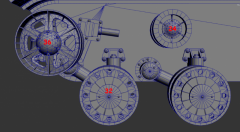
Example rollers modeling.
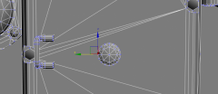
But there are exceptions in the form of independently standing/protruding simple cylindrical objects such as this pistol port with a diameter of 90 mm and 16 edges in the cross section.
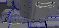
Tank cables are made of only 6 or 8 edges depending on the thickness.
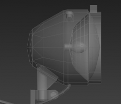
Lights are modeled in full, i.e. with a reflection and light bulb.


High poly
Rule number one: our main goal with high poly is not to make a hundred-million-polygon model, but to model all the elements such as locks, bolts and fasteners and to smooth out round surfaces. In other words, our high-poly geometry does not significantly differ from the low-poly version. But it is smoother and more detailed. In principle, we’re not dealing with high-poly geometry in the traditional sense of the word, but with medium-full poly.
We use Zbrush or another program for high-poly modeling, to bruise pieces made of soft metal. These are objects such as mufflers on exhaust pipes, tin mudguards covering the tracks, fuel tanks, and other pieces made of tin. We always sculpt welds, gas cuts, digits, stamps and all large uneven points on cast armor (other small reliefs such as flakes of paint, mud, rust are unnecessary), damage to rubber on the roller wheels. At the same time we bake all AOs and normal maps with such a geometry, using the DecimationMaster plugin in Zbrush to optimize the high-poly geometry. Additionally, we do not accept *.ztl format files or files in any other format for sculpting. We do not need them. We need only a medium poly geometry in *.max format.
For those parts that are baked with a high-poly geometry in low poly, it is mandatory to adhere to the following rules:
- In a high-poly model with a drop in height relative to the low-poly model, you cannot make edges parallel to the vertices of the normals in the low-poly model, i.e. perpendicular to the polygons of the low-poly geometry.
- When modeling joints (junctions of armor plates, hatches) or apertures, we do not make them separate pieces above the main high-poly geometry! Joints must be concave and embedded! This requirement is due to the fact that we remove not only the normal map from the high-poly model (in which there is no difference at all between the approaches), but also the AO.
- Also, due to our texturing technology, you must indicate the material in the high-poly model distribute IDs of materials depending on their real material (cast and rolled armor, metal, fine metal, wood, cloth, rubber etc.). This is best done at the very beginning of the project, otherwise it will be very difficult to mark out IDs on high-poly objects from Zbrush. A list of real materials and the material itself is attached.
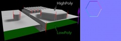
To obtain such a result when baked.
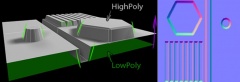
It is necessary to make the slope to get the following result.

LODs
Maximum distribution of triangles:
- LOD00 140,000 triangles
- LOD01 70,000 triangles
- LOD02 5,000 triangles
- LOD03 500 triangles
In-game FOV camera – 90 degrees
A more precise amount of triangles in a low-poly (game) model and in the LODs for it is confirmed for each tank separately. It can also change to be lower during the creation process.
Switching between LODs should be barely noticeable. If the optimization of a group of triangles is too noticeable (for example, removing wheels, tracks and other parts of the suspension on lod02), the null LOD must be rebaked to the current, optimized one. In doing this, we use the same textures that are used for the null LOD without spawning new ones. We look for free space in the texture map.
Note: groups of LODs in 3DSmax are the only point in our process where we do not use underscores in the title before enumeration. This is for historical reasons.
Important! If the complex configuration of parts in the suspension does not allow for cutting enough triangles to reach the acceptable minimum, but removing elements of the suspension would be too noticeable when switching between LODs, we make a primitive geometry in the LOD that ‘captures’ and repeats its main volumes, and bake the entire suspension into this geometry specially for the LODs. We do not make an additional texture while doing this – we place it all in the tank’s hull.
Tracks
- All tanks have 4 vertically tiled tracks which will scroll. Please note, this is important: 4, not 3 or 6.
- The number of segments in a low-poly model around the drive wheel must be divisible by the number of teeth where the wheel meets the tracks. I.e. by 5 teeth. For example, we make 5 or 10 or 15 splits – as many as are necessary for the texture to smoothly scroll along the track geometry, without sharp bends on the splits.
- The texture around the drive wheel must be clearly mapped – one tooth = one track. No guess-work can be used here! Distinctly – segments corresponding to one step of a tooth are a fourth of the map in height.
- We use alpha test to make all the voluminous elements that influence the track silhouettes in the texture, we do not use a geometry under any circumstances (for example, the teeth along the internal part of the tracks or the external projections of the tracks).
- To animate the suspension, it is necessary to make a split on the track precisely underneath each wheel, which will ‘roll along the ground’. If the wheel touches the upper part of the track also, then a split is required above as well.
- Tracks only use AO mapping.
- In the texture map, tiles from 7 to -7 are allowed on the tracks.
Skin modifier for tracks
The skin modifier is applied to tracks. Bones are created specially to animate the tracks. They influence nothing but the tracks. All the track animation is procedural, nothing has to be animated in 3DSmax. We need the bones to imitate the behavior of the real tank’s tracks: correspondence to the surface on which the tank travels, bending and tension on the tracks when noticeable (for example with the tank).
The wheels are procedurally animated, reacting to uneven surfaces. The tracks will repeat this reaction. What is required for this:
- Along the bottom of the track, we cut a geometry with additional splits based on the amount of carrying wheels.
- Each split is precisely underneath the center of the corresponding wheel.
- In the center of the carrying wheels we create a bone which will duplicate the behavior of the wheel. We name this bone the same as the wheel, but with the prefix bone_.
- We roughly skin each split to the corresponding bone.
- All the vertices that don’t touch the ground and are not attached to the bone of the road wheels, we skin to the root bone.
We will also animate the upper section of the tracks that hangs down between the guide rollers. To do this, we must:
- Add splits to the tracks above the supporting wheels, all supporting directional parts, generally above everything that the tracks hang on from above.
- Add two to four splits in the middle of the spot where the track should hang.
- Drop the track down to the state possible for this tank. We look at the references.
- Create bones in the centers of any ‘sags’ with the same axis direction as the bones on the lower row of the track.
- Name the bones: bone_phx_track_r_top_01, bone_phx_track_r_top_02 etc. Number them from front to back based on the tank’s movement direction.
- Attach the corresponding vertices to it.
In creating bones for tracks, the following must be considered: we add the suffix _phx only on the upper, dangling bones. The lower bones collide with the ground, but do not have physics animations. They do not need such suffixes.
More detail about this in the section: 2.2. Bones. Animation skeleton
Alpha channel for tracks.
Tracks use a two-sided shader. With the help of the alpha channel, we try to emulate the volume of the tracks. The geometry can be multi-layered to emulate external and internal surfaces. The configuration and profile of tracks is usually unique and must be chosen. Here is an example of using a multi-layered geometry to emulate the external surface:

Damaged track model. The model of a broken track also uses the Skin modifier. But with an amendment so that only the lower vertices of the broken track, ‘lying’ on the ground, are skinned to separate bones. All other vertices are skinned to the root bone. Bones for the drooping of the tracks during movement are not involved with the skin of a broken track.
Creating tracks
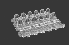
high-poly track model and duplicate it 6 times, since we need 4 tiles and baked unique tracks
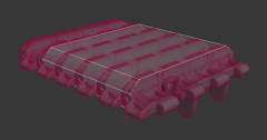
Step 2) Create a low-poly out of spacers step-by-step start with the external size
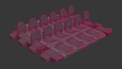
Step 3) then from the reverse side
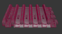
Step 4) Since this volume continues from the reverse side as well, add these surfaces to describe the internal volume of the track.
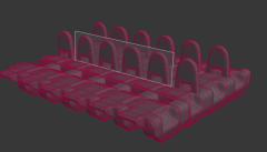
Step 5) Next, add a spacer for the ridge. In this case it practically has no volume, it is very thin, so we make do with a single spacer. The reverse side and the second row of ridges will be duplicates of this surface in the texture map.

|
Note: all small spacers are duplicated along the track’s line of symmetry. There is no need to litter the UV with elements that are basically identical. We need the track to remain as detailed as possible. |
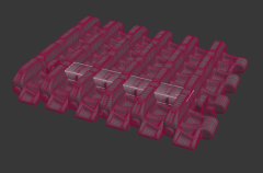
Step 6) The volumes of the thresholds of the tooth apertures for the drive wheel will also be placed by overlap in the texture map, since geometrically the high-poly is identical in this place.
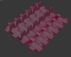
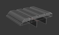
Step 7) As a result, we get a fake volume like this
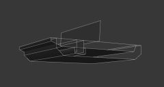
Step 8) Now we need to make the map. We map spacers vertically along the line of movement in such a way that the lower points on the map look forward along the X axis.
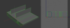
Step 9) The resolution of the baked texture is 2048x512, so it is desirable that the resulting spacers fit into 4 tiles, but if this is not possible and we end up with roughly 5, we simply press them together. If there are more, then we have overcomplicated the model and not made use of overlapping identical elements.
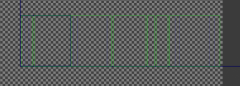
Step 10)Next we look at the model and realize that there is too much space between these spacers
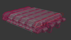
Step 11)If we leave the model as it is now, then it will be very clear in the game that the model consists of infrequent spacers and a poor volume simulation.
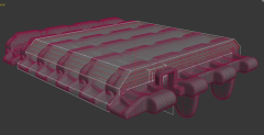
Step 12)In order to avoid this, we add additional internal spacers between the ones we already have. These new ones are duplicates of each other, i.e. overlapping UV shells, so we need to economize on space.
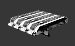
Step 13)Now we consider the model ready and we bake it. The initial track bake is never perfect, it has to be touched up by hand in Photoshop.
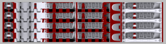
Step 14)We cut holes in the alpha channel where they are present in the high-poly model.
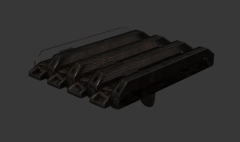
Step 15)As we can see, the volume is too small. For this reason, we add another volume describing the cutaways on the cleats.
Step 15)
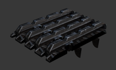
Step 15)


Texture map
The final model should contain two texture channels: the first for all the base textures and a second for the camouflage tiling. In creating the map, it is important to take into account that it will contain the internal part of the hull and the engine. The texel is equal to 0.2 – 0.4 centimeter.
 Hull – 4096х4096
 Turret – 2048х2048
 Main gun – 2048х1024
 Tracks – 1024х512
UV1: It is important to try to make fewer seams. This particularly concerns horizontal joints with normals aimed upwards:

UV2: The camouflage tiling takes place along the second, seamless mapping channel (UV2). We make this channel using spherical mapping. The center of the sphere is a little below the lowest point of the tank, and the entire tank is mapped into a seamless sphere.
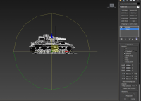
In some cases, if the turret configuration does not allow for applying coloring along a single texture map with the hull, it is acceptable to have a spherical map for the turret and gun separate from the hull. It makes sense to make the final map when all the parts of the tank are done on all LODs. This is so that the camouflage applies identically for all LODs. A script is also provided for convenience. How to use the script
- unhide all
- hide the skeleton, DM and Xray layers
- apply the script
- convert to editable poly
If you are working by hand, it is very important not to separate elements with the skin modifier. Otherwise it will disappear during conversion.
General mapping requirements
- Do not use auto-mapping!!!!!!
- If all the tank’s wheels are identical, you do not need to map them all in one place. Make two unique ones.
- Geometry which is almost invisible should be made with a larger texel (the reverse side of the gun mantlet, the bottom of the tank, the suspension sides looking inwards and all low-visibility surfaces).
- Map the objects to positions of the surfaces that are never visible.
- The internal section of the tank should be mapped separately with a scale of roughly 4 times more than the main texel (the ceiling of the internal section can have an even larger scale, since it is almost invisible).
- Try to make the object a whole one. If this cannot be done, place its parts in one spot. If you split an object into many small parts, useful space is eaten up by padding!
- The sides of the bottom can be mapped into one space.
- Various canisters, if there are several of them, do not have to be made unique
- We map the glass, reflector and light bulb of lights in a separate texture (we choose the light texture based on reference material).
Principle of selecting a cut Based on the reference, the relationship between the width of the cut and the distance between the cut is calculated. If it does not fit these values:
 type A 1/3 per section
 type B 2/5 per section
 type C 1/2 per section
 type D 1/4 per section
then it is rounded to the closest of these options and that option is used.


- Radiator grills and wire cloth are mapped separately. There are tiles for them.
- All hatches and not significantly protruding elements in the map are mapped to where these objects are located on the tank in reality. This is done so that when removing insignificant protruding elements in the very first LOD, we keep the hatches where they are in the null LOD.
- Wooden items should be mapped horizontally.
Requirements for baked textures
NormalMap – the normal map is baked via whatever means is most convenient to you (3DSmax, xNormal, Substance Designer) from the high-poly to the low-poly geometry with final definitions for smoothing groups in the low-poly geometry. It must be baked into a 16 bit TIFF. If the smoothing groups are changed, the normalmap will have to be retaken. The normalmap cannot be inverted. In our version, the green channel should ‘light up’ from below.

Ambient Occlusion (the dispersed lighting map) is baked from the high-poly geometry via whatever means is most convenient for you (3DSmax, xNormal, Substance Designer etc.).
Only shadows from the high-poly should end up in the AO, or, if necessary, only those from the low-poly geomtry! There should be no mix-ups in the shadows, shading from non-existent elements or any elements lacking shadows! The AO must be faithful!
Exceptions: there should be no hard shading under animated elements and elements that fly off when hit (AO must be illuminated for these elements). For example, the hull should have AO from the turret, but not from the gun, and not from a box on the side of the turret, since they change their position with the turret (when it turns) relative to the hull during gameplay. It’s best not to bake points like these faithfully on the hull, but to do them separately, for example from a conditional, fake turret that extends equally on all sides. Be sure to make a field for the hull to get the effect on the bottom. The turret must also be baked on a plane to emulate the hull.
The ColorID map is baked from the high-poly to the low-poly model. Before baking, you must set the ID of the material in the high-poly based on our material. This is best done in the initial stage. Materials will be set in Substance Designer based on this map. The map contains the colors which will be used to mix materials. They should be pure colors, without gradients etc. This map can be obtained directly in Substance Designer or 3DSmax.
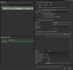
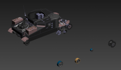
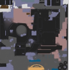
The result should be a map like this


Pipelines, development stages and work acceptance
We ask all our outsourcers to conform to these rules:
- Always keep us in the loop with regards to your model creation process to avoid serious alterations to the finished model.
- All stages of model creation must be confirmed with us.
- Tell us about any problems in the development process immediately so that we do not find out too late that deadlines have been missed because <...> – at that point it no longer matters.
- Please inform us about all independently detected flaws in models and textures which require further work – this will make both our work and your work easier and save time for all parties.
- If anything is unclear or questions arise about the pipeline, ask your questions immediately. We may be able to help you more quickly than you can solve the problem yourself.
Stages of model development and acceptance
The base mesh is the base geometry in 3DSmax format. At this stage, it is required to correctly name folders and files. Units of measurement, model turns and axes must be correctly set in the file. This model must be the base geometry (dummy) of the tank. It is important that the model’s size matches those of the diagrams or other references used to create the model in 3DSmax. This model is required to confirm all the real sizes of all the tank’s parts and objects (size of the hull and wheels, length of the gun, caliber), the armor angles, turret turn angles, gun aiming angles etc. Do not make any complex geometry. The file must include planes with diagrams (designated as textures) of the side, front and upper projections and other projections if they are present in the model references. Along with the *.max file with the base geometry, it is necessary to send all diagrams used as textures. It is also necessary at this stage to check the accuracy of the diagrams in terms of the alignment of large parts – the hull, turret and gun – in the following manner: the turret must turn on its axis without intersecting with the hull geometry. The same is true for the gun – it must not enter the hull geometry when at standby.
Low Poly – a model that meets our technical requirements – all the tank’s elements must be modeled and the number of triangles must correspond to the requirements of the null LOD. All low-poly objects which form the null LOD of the in-game tank must be named correctly in the *.max file.
High Poly – a model with tank elements modeled in detail including small bevels, locks, springs etc. If the file turns out too polygon-heavy (2 million triangles or more), then there is no need to clone all elements in the high-poly model that are duplicated in reality, for example wheels and tracks. The model must clearly match the historical prototype. It is important to remember that far from all diagrams are accurate to the last detail – sometimes photographs can be used to get a clearer picture of the character of a surface. In our experience, this stage is rarely accepted the first time around, since it will be demonstrated to our historical consultants who will offer their own observations. The names of objects in the high-poly model in the *.max file are not important to us – name them in whatever way is more convenient to you.
Sculpt – in this iteration we crumple all the tank’s tin parts. We always sculpt welds, gas cuts, digits, stamps and all large uneven points on cast armor (other small reliefs such as flakes of paint, mud, rust are unnecessary), and damage to rubber on the roller wheels. The designer can choose which program to use for sculpting, it is the result that is important to us: tin and fine bent iron must look natural and pleasant, welds and other uneven areas on a cast turret must look natural. The goal of this stage is to breathe life into our tank, show signs of use, add a sense of presence for the player.
UV – on our tanks, one texel is equal to 0.2 - 0.4 centimeters. In the game, the texel will be twice as large. Not all tanks and not all turrets or guns can fit into these borders. If they cannot, be sure to let us know and show us the model with the current texture map. We will decide whether it is viable to increase the texture resolution for this tank. We welcome reducing the resolution for small light tanks. It is possible that for some of them, the entire tank can fit into a 4K by 2K total texture space.
Bake – after this iteration, we must receive a correct AO, Normal Map and ColorID Map. The textures must correspond to the technical requirements. There should be no unpleasant artifacts, the model should look correct and pleasant. There should be padding where necessary, none where none is necessary. It’s important to remember that for rotating elements (wheels) a neutral AO must be baked. This is so that there is no lighting clearly from top to bottom.
After the bake is accepted, the other processes can be run in parallel and sent in when ready.
Bones’n’nodes – make bones and nodes for attaching machine guns and particles, name them correctly and orient them correctly. Set a skin for the objects requiring it (tracks, antennae, canvas cover, springs etc.).
LODs – make LODs for the tank and damaged parts. Distribute them across the layers ensuring that the names and pivots in the various layers and states match each other.
DM, XRAY – make a geometry and name it correctly.
Final model – the final model has all the geometry named correctly, the axes turned correctly, object matrices at the source size (100 percent scale along all axes), a correct hierarchy of all objects, bones and nodes, the tank uploaded into the engine with everything working. There are no errors in the upload (degeneration, undesignated smooth groups etc.).
Approve – acceptance of all the materials for the tank. In the root folder of the tank, there is a *.max file with the final tank ready for upload to the engine. There is nothing superfluous in the file, only the game model. It also contains *.tga format textures. The work folder with the file *_bake.max, which contains the scene with the high-poly and low-poly model ready for texture baking.