3D models for cockpits
Custom cockpit models
OLD‑WIKI.WARTHUNDER.COM (DEFUNCT)
Technical requirements for cockpit models
General Scene Requirements

- The scene must be fully compatible with Autodesk 3ds Max 2011
- Scene names must contain the full name of the aircraft with the postfix «_cockpit». For example: bf_109e_3_cockpit.max. Scene and texture names cannot contain capital letters or hyphens «-». Instead, use underscores «_»
- Stacks must be collapsed on all objects (objects must be Editable Poly)
- Models are made to scale using metric system units (System units = Meters)
- Display units may be whichever you want
- All objects must have their scale reset to 100, 100, 100 (use Hierarchy/Reset Scale)
- The cockpit should be positioned within the external model and oriented the same way (The X-axis points forward; the Y-axis is pointed to the left of the direction of flight; the Z-axis should point upward)
All objects in the scene must be composed into the following layers:
- Cockpit – the cockpit itself. All cockpit related objects go here
- LOD0 - undamaged state of the external model (is taken from the external model). Holes in the glass canopy and instrument panel go into this layer also
- GUN – flames from gun barrels and also bomb and rocket mount points (from the external model)
- nodes – animated pilot nodes linked to controls (are provided in the sample model)
Pivots for all non-moving objects must be at the center of world coordinates (World 0,0,0), the local axis must match the world axis. Pivots for gauge needles and aircraft controls must be at the point of rotation with one axis pointed along the rotational axis. In order to easily animate them. Since these objects will be animated particular axis of rotation (local x,y or z) is not important.
Model
Cockpit Geometry. Polygon Count
The model must contain 45-70K triangles for a single seat cockpit and 60-85K for a two seated cockpits. When making geometry, you should take into account the 360° camera view, as well as the fact that the game camera can move about 20-30cm in any direction from its neutral position. So you have to be careful to which invisible polygons are to be deleted when optimizing cockpit geometry. You may want to make a layer called «invisible» and store excessive polygons there (not to be exported). Faces without smoothing groups are not allowed. Even if it is a flat surface.
Smoothing groups must be present on all faces.
UV mapping. Texture Layout
UV coordinates must not exceed +-7.0 in any direction.
All faces must be mapped and have UV coordinates.
Otherwise there will be conversion errors.
It is a good practice, for ordinary geometry to have all mapping inside 0-1 UV space.
Naming Convention & Animation
Animation should be made in a 0 to 100 frame range for any animated object. A Note track is to be created in the Track View Dope Sheet with keys «start» at frame 0 and «finish» at frame 100 for one of the objects. For cockpits it is the throttle object. The game code reads the «start» and «finish» keys to determine the animation range.
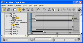
Track View - Dope Sheet «start» and «finish» keys
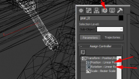
Animation controllers


Use only Linear Position, Linear Rotation and Linear Scale animation controllers.
Animation constraints are not allowed.
The names for moving (animated) objects in the cockpit are in the table below. The table also lists the initial and final positions of controls and instrument needles. Number and availability of objects depends on the cockpit you are making.
Animated objects:
| The name of the needle or device | Name in the scene | Position at frame 0 | Position at frame 100 |
| Controls | |||
| Aerodynamic Surfaces | |||
| Aircraft Control Stick | stick_elevator * | fully away from the pilot | fully towards the pilot |
| stick_ailerons * | full to the left | full to the right | |
| Pedals | pedals | left pedal forward | right pedal forward |
| additional parts available | pedals(1-8) ** | -- | -- |
| Flaps | flaps | retracted | extended |
| Trimmer | trimmer | nose down | nose up |
| Engine | |||
| Throttle | throttle | idle rpm | maximum rpm |
| add. | throttle(1-2) | -- | -- |
| Mixture | mixture | rich | lean |
| add. | mixture(1-3) | -- | -- |
| Propeller Pitch | prop_pitch | high pitch | low pitch |
| Supercharger | supercharger | off | on |
| add. | supercharger(1-2) | -- | -- |
| Radiator Flaps | radiator | closed | open |
| Weapons | |||
| Weapon 1 | weapon1 *** | neutral | pressed |
| Weapon 2 | weapon2 *** | neutral | pressed |
| Weapon 3 | weapon3 *** | neutral | pressed |
| Weapon 4 | weapon4 *** | neutral | pressed |
| Others | |||
| Landing Gear | gears | retracted | extended |
| add. | gears(1-2) | -- | -- |
| Instruments & Equipment | |||
| Aircraft operation and Navigation | |||
| Altitude (km or thousands of feet) | altitude_hour | 0 degrees | 360 degrees clockwise |
| Altitude (hundreds of meters or feet) | altitude_min | 0 degrees | 360 degrees clockwise |
| Altitude (10k meters or feet) | altitude_10k | 0 degrees | 360 degrees clockwise |
| Speed | speed | 0 km/h (knots) **** | maximum speed **** |
| Mach Number | mach | minimum M | maximum M |
| add. | mach1 | -- | -- |
| Rate of Climb | vario | maximum descent | maximum climb |
| Artificial Horizon Pitch | aviahorizon_pitch | maximum ascent | maximum descent |
| Artificial Horizon Roll | aviahorizon_roll | maximum roll to the right | maximum roll to the left |
| Bank Indicator | bank | ball in the leftmost position | ball in the rightmost position |
| add. | bank(1-2) | -- | -- |
| Turn Indicator | turn | to the left | to the right |
| add. | turn(1-2) | -- | -- |
| Compass | compass | 0 degrees | 360 degrees counterclockwise |
| add. | compass(1-4) | -- | -- |
| Clock | clock_hour | 0 degrees. 24 hours | 360 degrees clockwise |
| clock_min | 0 degrees. 60 min | 360 degrees clockwise | |
| clock_sec | 0 degrees. 60 sec | 360 degrees clockwise | |
| G-Meter | g_meter | max negative-g | max positive-g |
| g_meter_min | max negative-g | max positive-g | |
| g_meter_max | max negative-g | max positive-g | |
| Ammo Counter | ammo_counter(1-8) | full | empty |
| Ammo Empty Lamp | ammo_counter(1-8)_lamp | not animated | not animated |
| Engine | |||
| Maniforld Зressure | manifold_pressure | 0 | maximum pressure |
| add. | manifold_pressure | -- | -- |
| Revolutions (single needle instrument) | rpm | 0 rpm | maximum rpm |
| add. | rpm1 | -- | -- |
| Revolutions (dual needle instrument) | rpm_hour | 0 degrees | 360 degrees clockwise |
| add. | rpm1_hour | -- | -- |
| Revolutions (dual needle instrument) | rpm_min | 0 degrees | 360 degrees clockwise |
| add. | rpm1_min | -- | -- |
| Oil Pressure | oil_pressure | minimum pressure | maximum pressure |
| add. | oil_pressure1 | -- | -- |
| Oil Temperature | oil_temperature | minimum temperature | maximum temperature |
| add. | oil_temperature1 | -- | -- |
| Water Temperature | water_temperature | minimum temperature | maximum temperature |
| add. | water_temperature1 | -- | -- |
| Cylinder Head Temperature | head_temperature | minimum temperature | maximum temperature |
| add. | head_temperature1 | -- | -- |
| Carburetor temperature | carb_temperature | minimum temperature | maximum temperature |
| add. | carb_temperature1 | -- | -- |
| Fuel Gauge | fuel | empty tank | full tank |
| add. | fuel1 | -- | -- |
| Fuel Pressure | fuel_pressure | 0 | maximum pressure |
| add. | fuel_pressure(1-3) | -- | -- |
| Others | |||
| Gear Down. Green Lamp | gear_lamp_down ***** | not animated | not animated |
| Gear Up. Red Lamp | gear_lamp_up ***** | not animated | not animated |
| Gear in Transition Lamp | gear_lamp_off ***** | not animated | not animated |

* - stick_ailerons should be parented to the stick_elevator. If the control stick is made of one object (and usually it is), it is necessary to create a stick_elevator fake object (an ordinary small box will do) and put it in the hinge point of the control stick joint.
** - pedals can be a complex parallelogram mechanism. In this case, all objects related to pedals need to be labeled pedals1, pedals2, pedals3 etc.
*** - triggers on the control stick must be parented to stick_ailerons and named weapon1 (machine guns), weapon2 (cannons), weapon3 (bombs, rockets).
**** - usually the speedometer has a nonlinear scale. It is necessary to animate the needle in order to display speed in a linear manner. For example, if the maximum speed according to the instrument is 500 km/h, then for every 2 frames the speed must increase by 10 km/h on the instrument.
***** - these names are assigned to billboards, which have an illuminated lamp texture.
Materials & Textures
Several diffuse textures, normal and specular map textures are used for a model.
- body – primary texture set for our cockpit. Diffuse+normal+specular
- glass – glass texture. Diffuse only
- glass_dmg – oil stained glass (for battle damage). Diffuse only
- gauges - gauge dials and casings texture set. Diffuse+normal+specular
- gunsight – gunsight texture set. Diffuse+normal+specular
- labels – an optional texture set for cockpit text labels on billboards
- boxes – an optional texture set for equipment (radio control boxes etc.) that did not fit into the primary body texture. Diffuse+normal+specular
Diffuse map (with or without an alpha channel) is a separate texture.
Normal and specular maps share one texture with specular map placed in the alpha channel. Use optional textures carefully. For example if you have boxes texture with many text labels written on equipment - the remaining labels can be accommodated in the gauges texture. So we can skip creating separate labels texture.
The rule is the fewer textures the better.
Diffuse Textures
The default usual texture dimensions are the following:
- body (hull) – 4096x4096x24bit (no alpha). If the cockpit is small then a smaller size can be used
- glass – 1024x1024x32bit
- glass_dmg – 1024x1024x32bit
- gauges – 2048x2048x32bit or 24bit. Up to 4096 pixels for a multiseated cockpits with many gauges
- gunsight – 1024x1024x24bit (no alpha). No gunsight glass texture is required. Only gunsight body
- labels – 1024x1024x32bit. As required up to 2048
- boxes – 2048x2048x24bit (no alpha). As required up to 2048
glass_dmg texture is needed only when aircraft engine is located in front of the cockpit.
Always use the power of 2 for texture sizes. Aspect can be nonsquare. But it is better to plan your texture layouts keeping square sizes in mind.
An example of a, complete fighter cockpit texture set:
- f3f_1_cockpit_body_c.tga
- f3f_1_cockpit_body_n.tga
- f3f_1_cockpit_glass_a.tga
- f3f_1_cockpit_glass_oil_a.tga
- f3f_1_cockpit_gauges_a.tga
- f3f_1_cockpit_gauges_n.tga
- f3f_1_cockpit_gunsight_c.tga
- f3f_1_cockpit_gunsight_n.tga
- f3f_1_cockpit_labels_a.tga (optional)
- f3f_1_cockpit_labels_n.tga (optional)
- f3f_1_cockpit_boxes_c.tga (optional)
- f3f_1_cockpit_boxes_n.tga (optional)
The endings are added to the files of textures:
- «_c» postfix is for textures without alpha channel
- «_a» postfix is for textures with alpha chanel
- «_n» postfix is for normal map textures with specular map inside alpha channel
Important! Please do not forget to add required post-fixes to files. As the engine uses them to choose compression method for a texture.
You can find additional textures, used by cockpit in the sample model archive.
Tip for graphics software suites with layer functionality. It is better to store diffuse, damage, normal map and specular maps all in one file. The resulting combined names will be (in case of Photoshop):
- f3f_1_cockpit_body.psd
- f3f_1_cockpit_gauges.psd etc.
Normal and Specular Textures
The normal map and specular maps are the same size as the primary diffuse texture. Normal map uses RGB channels and Specular map uses an alpha channel. It is good to keep normal maps as bump (height maps) in your layered source document before the NormalMapFilter conversion. Converted (blue) normal maps in layers are better used only for minor corrections. Use filter default settings for height to normal map conversion: Min Z = 0, Scale = 8.
The normal map Y (green) channel must NOT be inverted.

You should get the following look after the NormalMapFilter conversion. Convex parts look as if they are lit from below.
The normal map must include minor details and relief which is "expensive" to do with geometry: rivets,
washers, etching, etc. The specular map should emphasize defects from everyday use of machinery: chips
and scratches on the paint, traces of abrasion on bolts, rivets and ribs of metal parts.
The following brightness values are recommended for the specular map:
- Primary surfaces (paintwork): K~80-90% (40-70 RGB)
- Bare metal (chips, wear) K~20-40% (170-210 RGB)
Materials (the order of material IDs)
Cockpit objects must have have a single Multi/Sub-object material, named «cockpit» assigned to it.
Sub-Object materials:
- (1) – glass
- (2) – body
- (3) – gauges
- (4) – gauges_dmg (damaged instrument glass)
- (5) – collimator or sight
- (6) – collimator_glass or sight_glass (for gunsight glass)
- (7) – bullet_glass* (canopy glass holes)
- (8) – bullet_metal* (holes in the hull)
- (9) – labels (optional)
- (10) – boxes (optional)
- (11) – flare_red** (red lamp flare)
- (12) – flare_green** (green lamp flare)
* - you can make separate Multi/Sub-Object, material for bullet holes.
** - you can make separate Multi/Sub-Object, material for lamp flares. Color and quantity may vary as necessary.
No special material is required for glass_a_dmg texture. Because it is swapped in game with ordinary glass texture when oil radiator is damaged.
Text labels with alpha cut letters are not allowed. Because alpha is eaten out quickly by texture mips. So the text becomes unreadable. «No degradation» flag is not available for cockpit textures. It has limited uses.
Tips for users with advanced graphics software suites
It is a good practice to keep the size of source files low. For *.psd files for example it is better to stay under 1GB for a 4k texture. Low file sizes, are more convenient to work with. Primary size eaters are ordinary layers with masks. Using them on every occasion can increase the size of the file dramatically in no time. Use masks with care and only where really necessary. Please do not use 4k masks just to change the transparency of several pixels in a layer. Solid color fills with masks may be used. They are not size eaters. Keep reasonable layer count so any element, of the texture is easily editable. Not too many but not too few. Cockpit layer names and format example:
- uv – rendered uv template can go here. The topmost layer. Hidden by default.
- gauge_dial_rpm
- color_handle_throttle_fs_37038
- overlay_pedal_left
- label_warning_landing_gear
- color_body_fs_34128 etc.
Layers may have sensible names which are easy to understand. For your convenience. In the example above Federal standard 595C colors are used for precise color description. Using the default layer names Layer 1, Layer 2 etc. may become uncomfortable in the long run.
Recommended names for layer groups:
- s – specular
- n – normal
- ao – rendered ambient occlusion
- lines – rivets and paneling
- text – text and service labels
- dirt – dirt and scratches layers
- volume – hand painted light/dark volumes
- color or c – primary colors for a cockpit
Additional layer groups suggestions:
- electric_radio_equipment
- electric_circuit_breakers
- control_throttle_quadrant etc.
It is better not to rasterize text layers. So that they can be easily edited anytime.
Ambient Occlusion
An ambient occlusion layer must be rendered at least for the primary cockpit texture. To have nice ambient shadows. You can use mental ray Renderer for these purposes. Select Ambient Occlusion (MR) when adding a component in the Output section of Render To Texture dialog. Use Edge Padding of 2 pixels. Play with mental ray Samples and Falloff parameters to get the desired look. Do not forget to switch to mental ray renderer in the Render Setup dialog window (F10).
Ambient occlusion must be rendered against a white background. In Photoshop (or similar software) use «Multiply» layer blend and place AO layer group on top of the layer stack. Play with opacity, as you see fit to get a good looking result. It is advised not to overshadow the cockpit. Please note that there will be static shadows rendered in places where we do not want them to be. On moving control surfaces or under pedals for example. Keep this in mind. Such places will have to be adjusted manually.
Other Notes

Glass bullet holes for damaged state are made with billboards placed near damaged surfaces (you can use texture provided with the sample model). Metal holes in the fuselage and instrument panel are made the same way. Player must get a visual notice when the aircraft is damaged. You can paint dirt on cockpit glass along the framework. With up to 40% opacity. Bare metal for chips and wear on the diffuse texture have to fall within 90-120 RGB range. Cockpit textures must not be clean. You can add traces of everyday use (wear & tear) with diffuse and specular textures for better realism.
Properties for all objects in the scene, are set with Object Properties Editor. Objects are treated as ordinary geometry. DagorMat2 materials with appropriate shaders have to be assigned for all objects to export. Please visit Dagor Tools chapter of the aircraft design document for information. Cockpits are exported the same way as aircraft. However, they have only 2 files for the cockpit model:
- %aircraft_name%_cockpit.lod00.dag - aircraft cockpit and LOD0 file.
- %aircraft_name%_cockpit_anim.a2d - animation file.
Good luck and we can't wait to see what you make.